P·09 · Mechanical
Modular Catamaran Hull: Tow Tank and Multiphase CFD
A modular, instrumented catamaran hull tested to Froude 0.7, and a multiphase CFD model made mesh-independent at up to 75% lower compute cost.
At a glance
- 75%less CFD compute, holding a consistent, mesh-independent drag prediction
- Fr 0.7highest Froude number tested in the tow tank
- ~95%agreement between CFD drag and tow-tank drag
- Where
- MIT Arcturus
- Role
- Mechanical engineering member
- Status
- Complete
- ANSYS Fluent
- ANSYS Meshing
- Multiphase CFD
- SST k-ω turbulence model
- Mesh independence study
- Resin 3D printing
- Laser cutting
- Arduino
- MPU-6050 IMU
- XBee telemetry
- Tow-tank testing
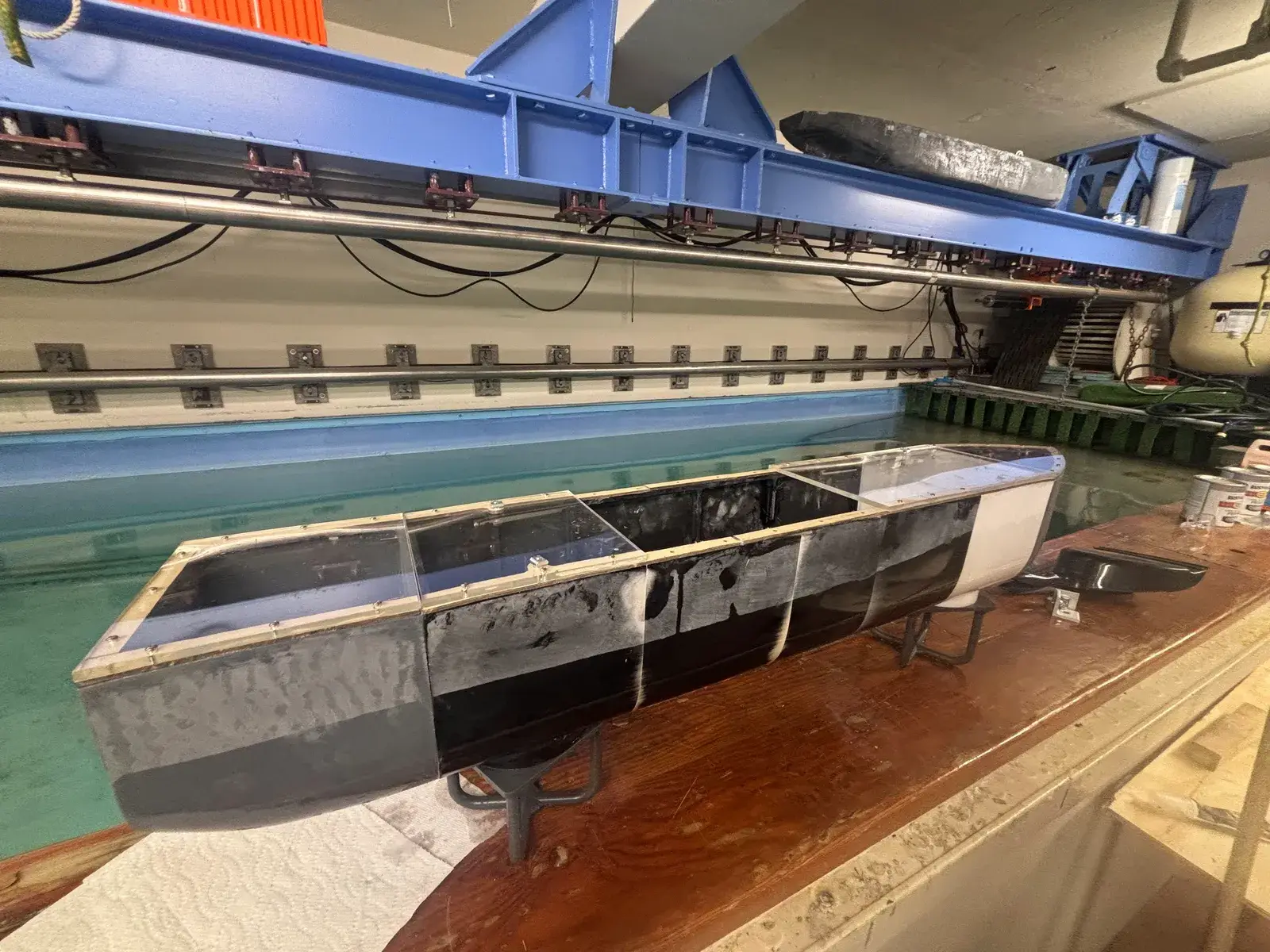
The problem
At the 2024 Arcturus competition, our autonomous boat’s hull did not produce a clean flow field and often pushed water onto the deck. This year we redesigned the hull to stop that.
We kept a catamaran layout. Catamarans have a high metacentric height, which gives them strong roll and pitch stability, and two slender hulls reduce drag. Their weakness is a lower range of angular stability than a monohull.
There is also a scale problem. Most hull research scales down large designs, and that often fails at our size because weight distribution, buoyancy and structural constraints do not scale the same way. We needed our own data at our size, both from the tank and from simulation.
Approach
A modular hull
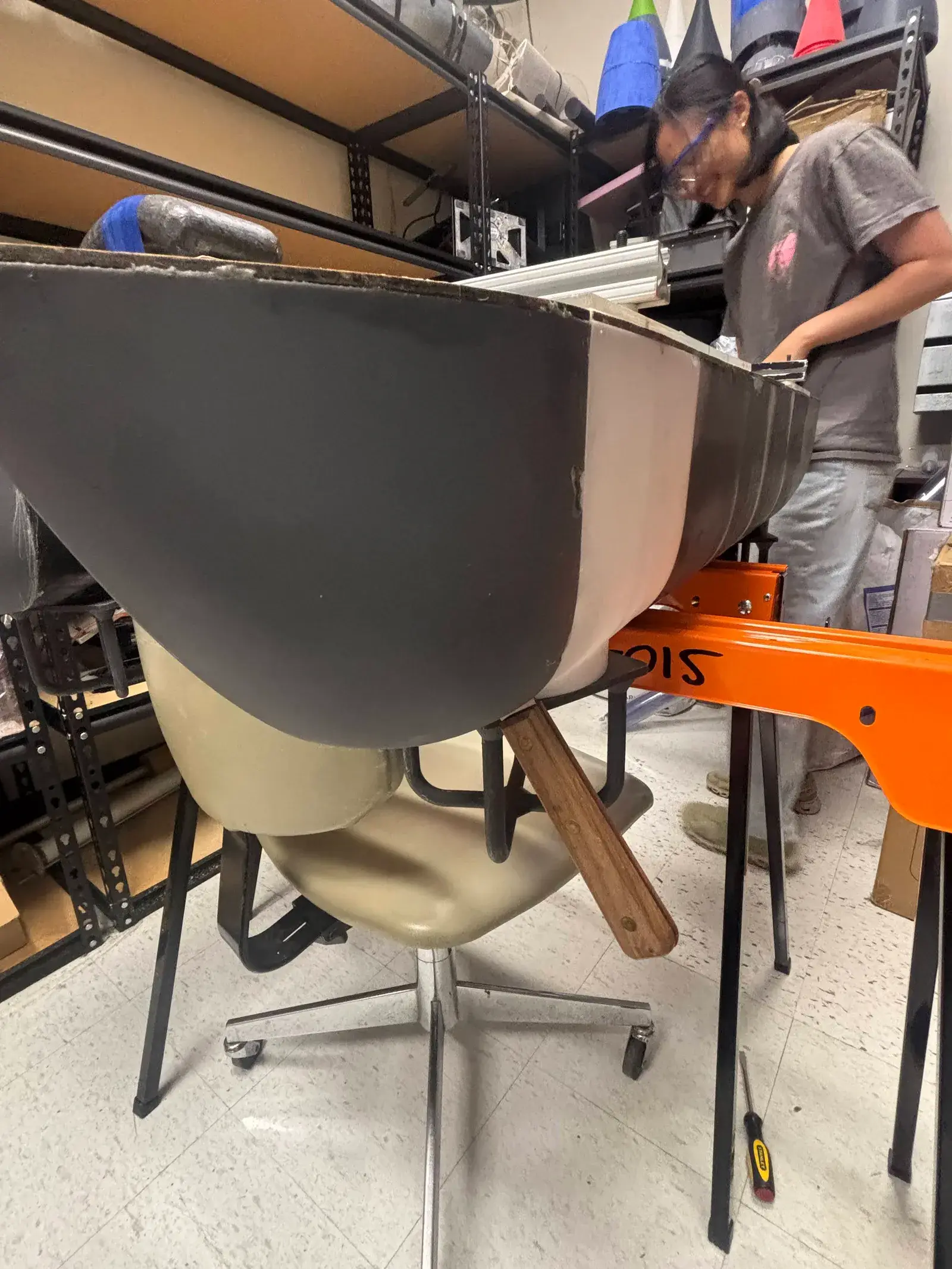
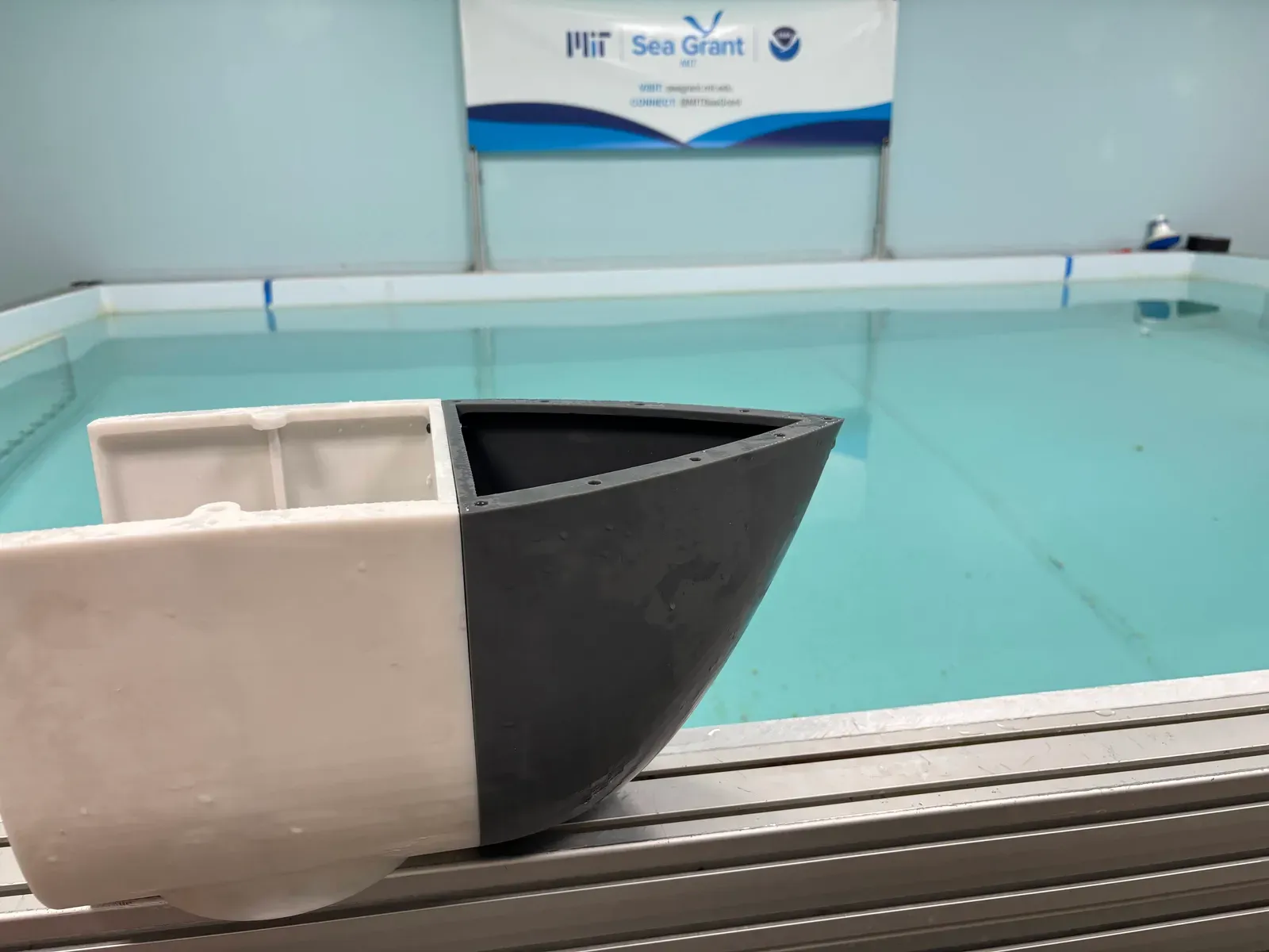
Our resin printer’s bed was too small to print a hull in one piece. We turned that into a design choice: each hull prints as a bow module and a stern module around a common center section. A new bow or stern design means reprinting one module, not the whole hull, so the same center can carry many test designs. The attachment method follows a 2020 MIT study of a similar modular hull.
The mechanical lead and I built the 3D model of the hull together. My main task was the modular attachment system.
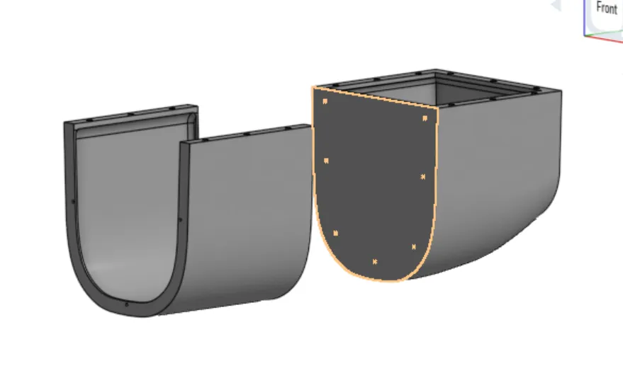
Sealing it
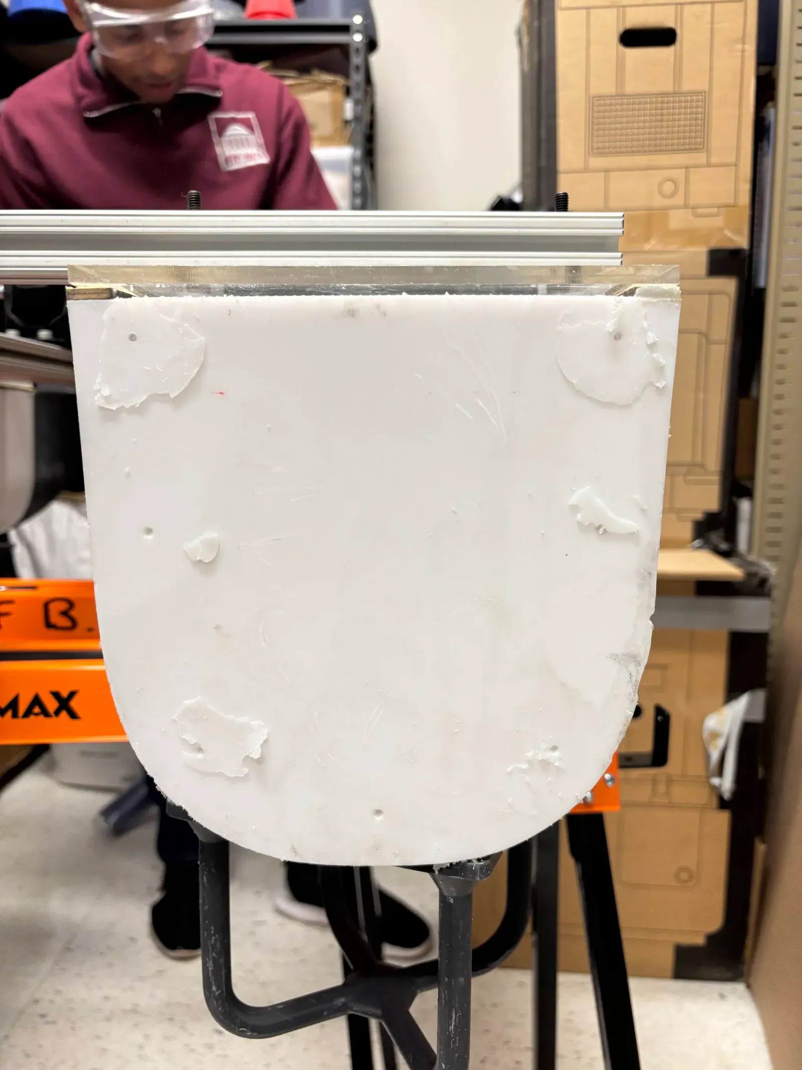
After resin printing, I sealed the hull with silicone to stop flooding. Acrylic lids, laser cut, close the tops of the hulls, sealed against the hull with natural rubber gaskets.
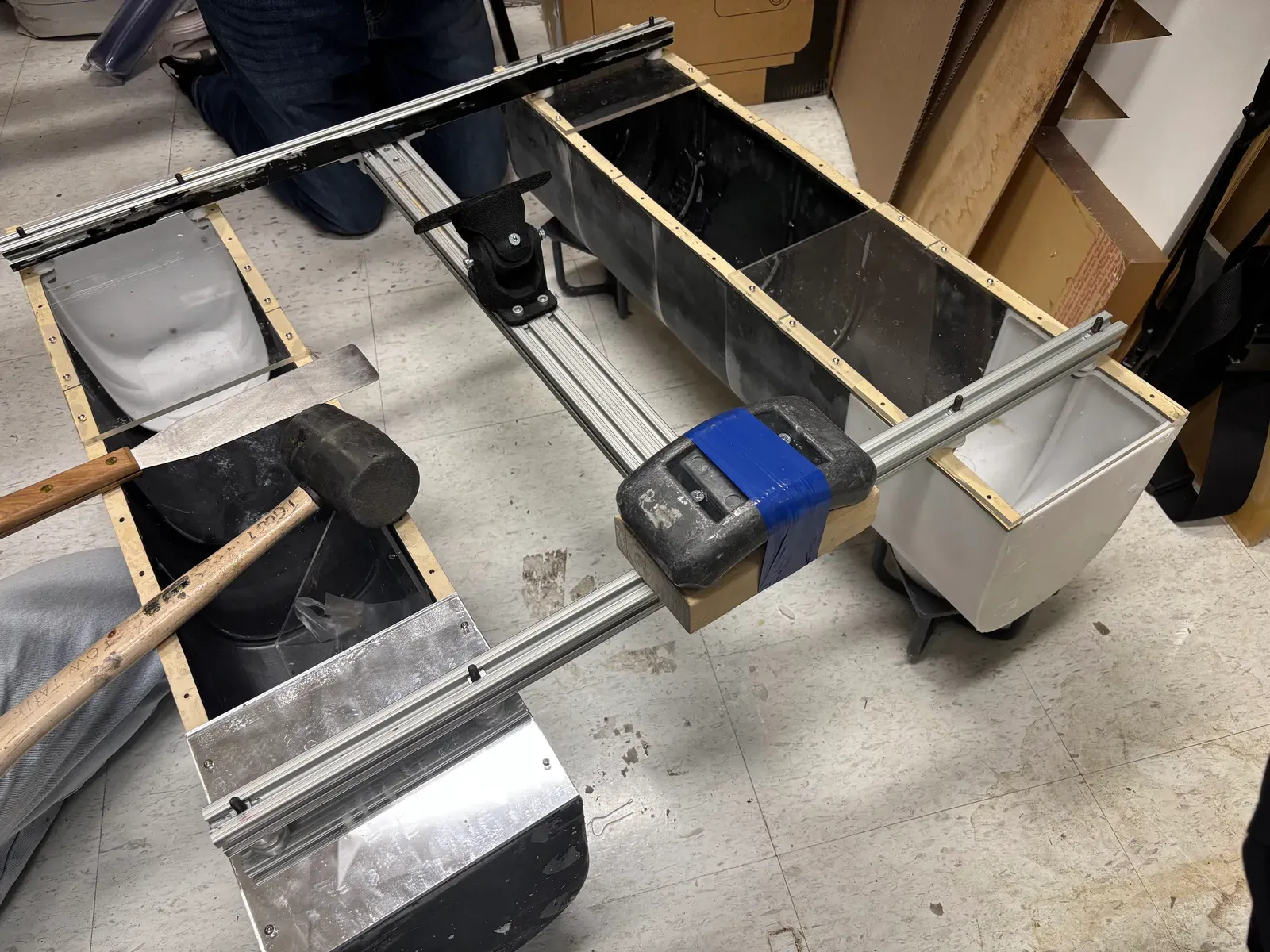
Instrumentation
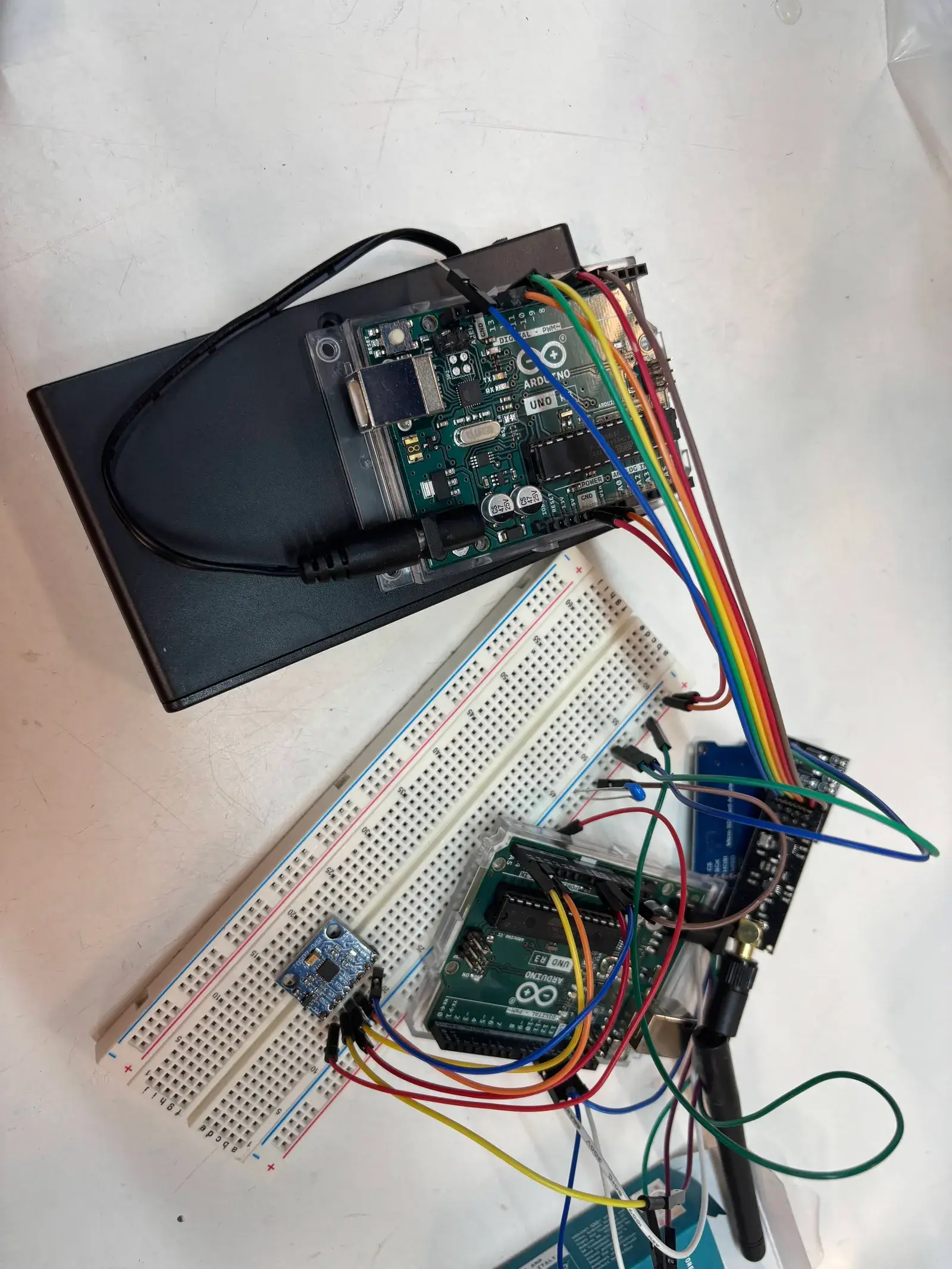
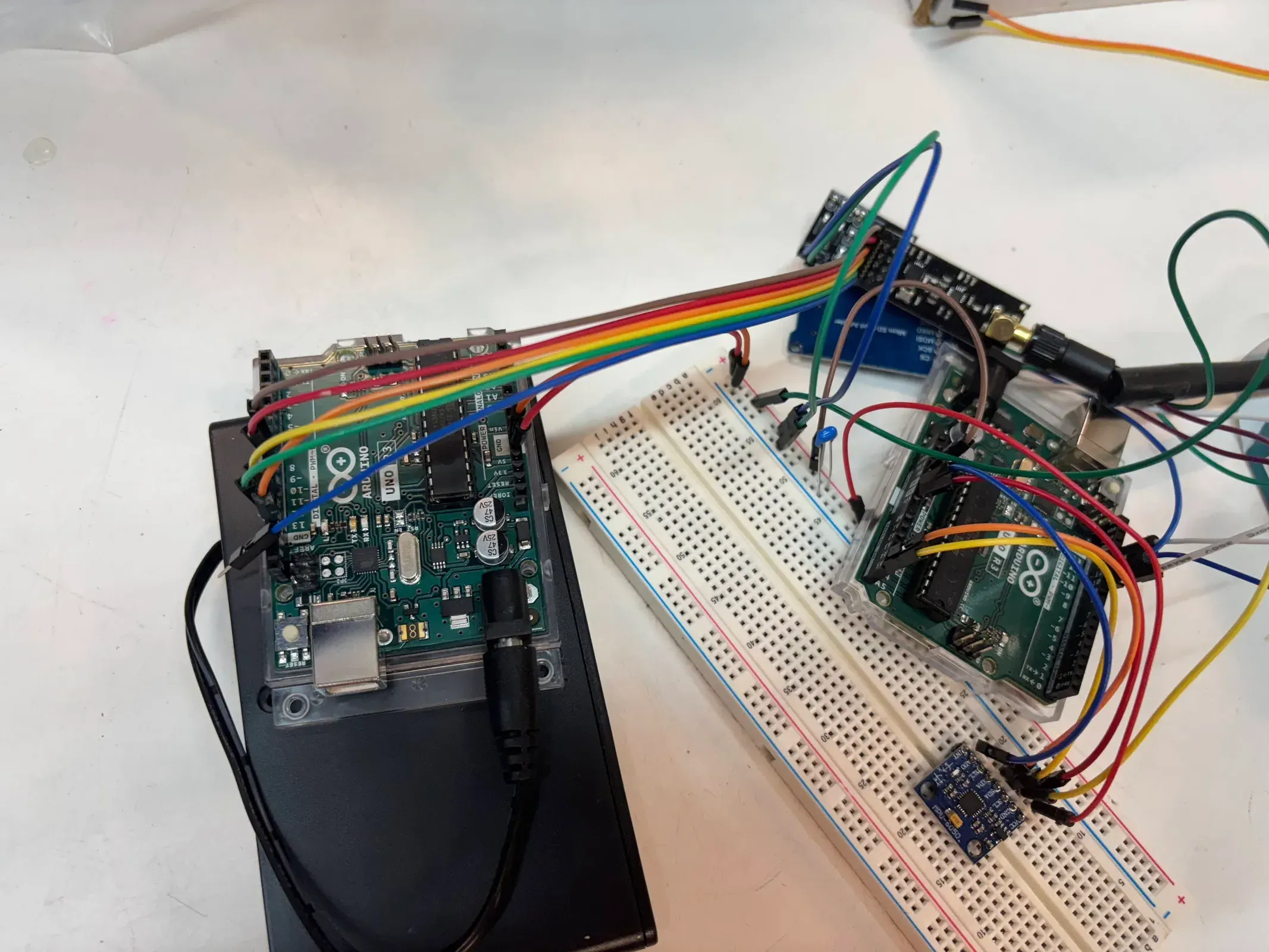
I built the data-acquisition system on my own. An MPU-6050 accelerometer on an Arduino logs motion data on the boat, and a DigiXBee radio (rated to 1,100 m) streams the data to shore in real time.
Tow-tank testing
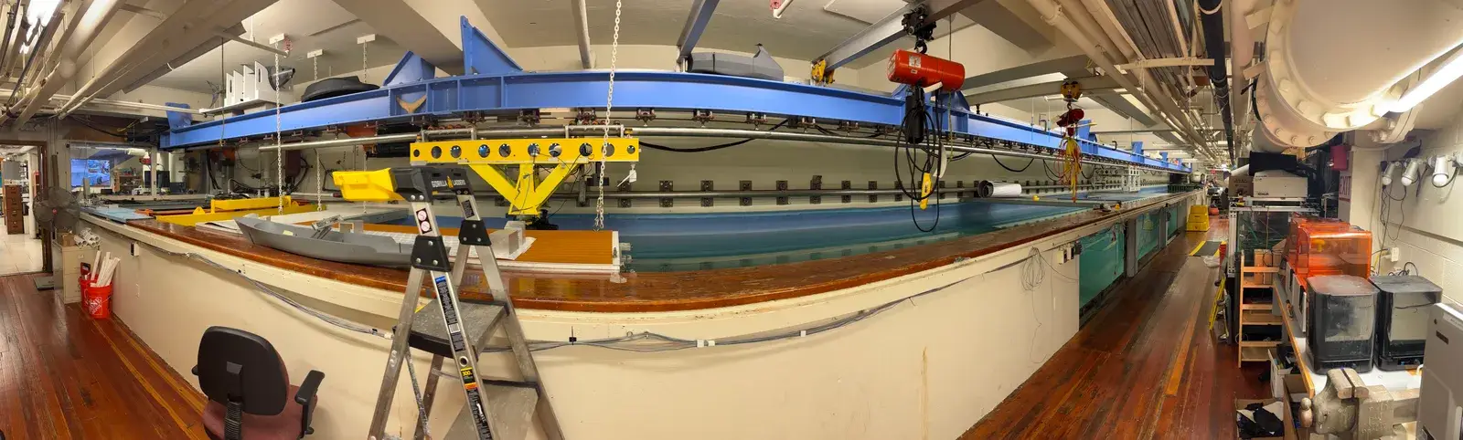
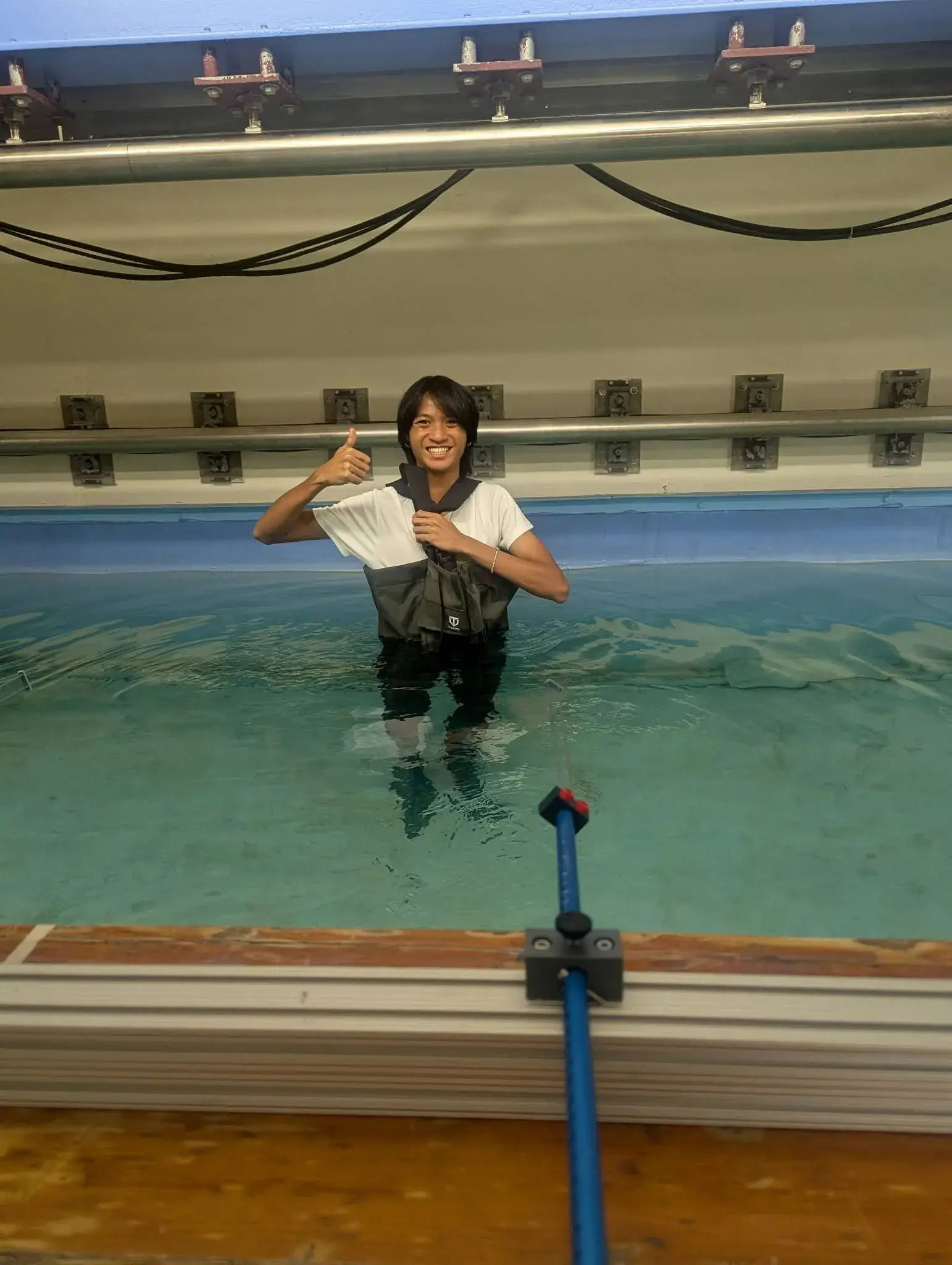
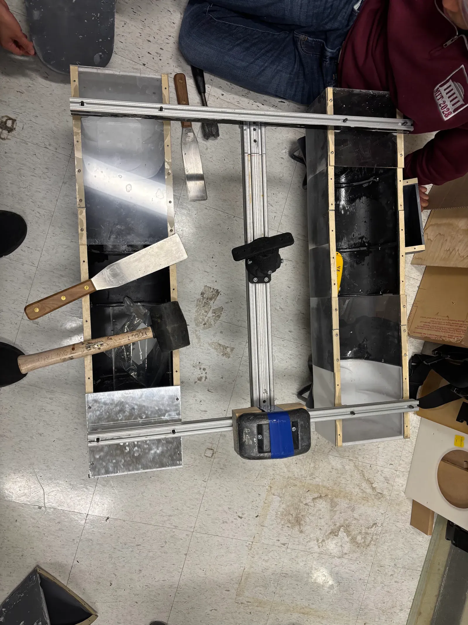
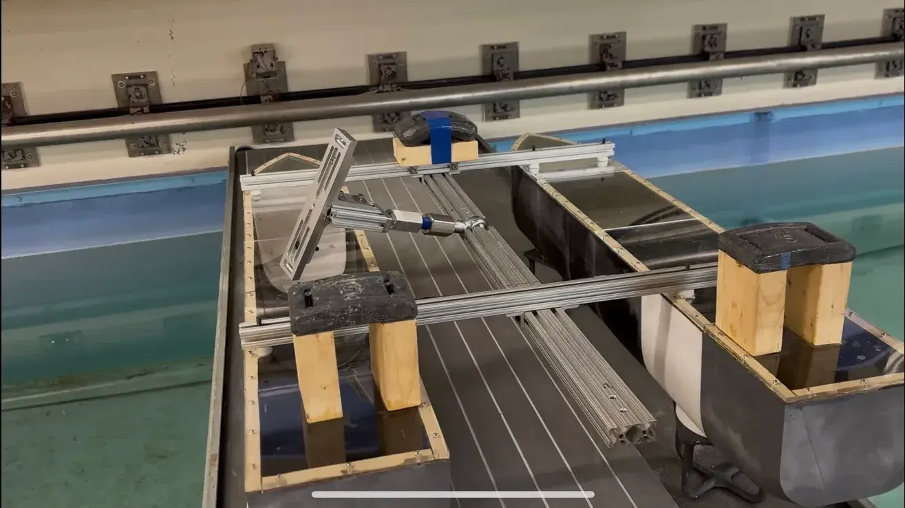
We mounted the boat to the tow-tank arm through a universal joint and towed it at speeds up to a Froude number of 0.7. A tow tank captures the air-water interaction and turbulence that simulation alone struggles with, so it is our ground truth. I ran assembly and disassembly at every session, kept every interface watertight, and kept the electronics reachable for calibration.
The bow redesign
Early runs showed good directional stability, but the bow let water in at higher speeds. With the mechanical lead, I revised the front modules, refining the curvature and the attachment tolerances and re-engineering the mounting holes so the new bow still fit the modular system. The new bow improved buoyancy at the front and reduced frontal drag. Because only the front module changed, a new bow could be attached, sealed and tested within hours.
Engineering detail: the CFD
Tow-tank testing is the gold standard, but every test costs a print and a tank session. I built a CFD model to screen design changes before we commit to building them.
Setup
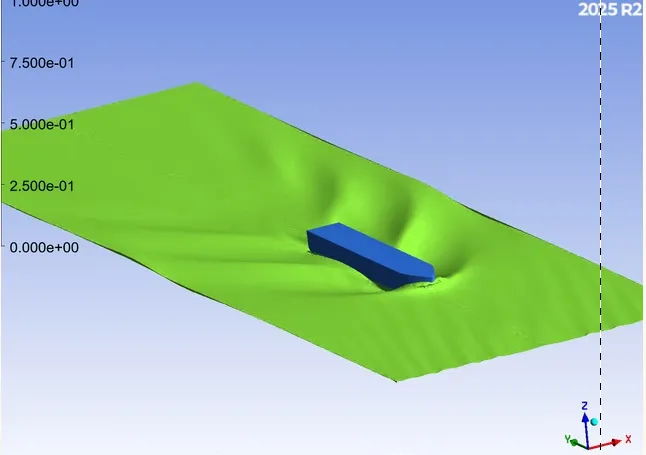
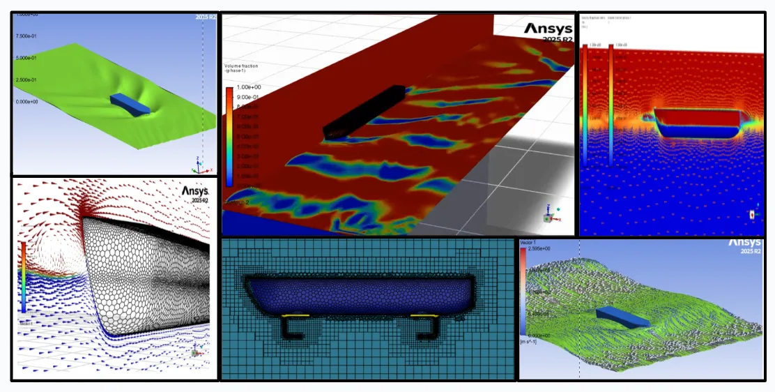
I ran steady-state CFD for drag and lift, and multiphase CFD in ANSYS Fluent to capture the air-water interface around the hull. The domain models calm water with a symmetry plane along the boat’s centerline. The hull has cylindrical supports, thruster mounts and filleted transitions, which make it hard to mesh.
Mesh
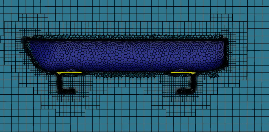
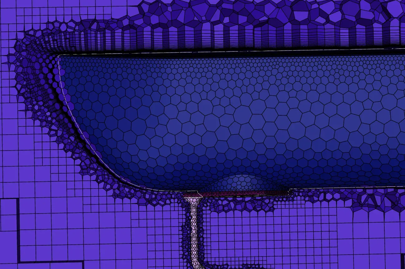
- Hybrid mesh: hex-dominant cells near the hull, tetrahedral or polyhedral cells in the outer domain, generated in ANSYS Meshing and checked for orthogonality, skewness and growth with Fluent’s mesh diagnostics.
- Boundary layer: I used the SST k-ω turbulence model, which needs the viscous sublayer resolved. I ran coarse pre-runs to estimate wall shear, recalculated the first-layer height from it, and repeated until y+ sat between 0.6 and 1.5 over 90% of the hull surface.
- Inflation layers: on the cylindrical supports and thruster bases, where velocity gradients are steepest, with growth kept smooth over curves and fillets to avoid solver instability.
- Free surface: a refinement zone around the interface that extends into the near wake, so the wave pattern holds its shape without numerical smearing.
Mesh independence
I compared three mesh levels, refining cell size and adding layers until drag, wall shear and pressure along the hull stopped changing. I steered each refinement step by the local residuals and convergence trends. The final mesh holds a consistent drag prediction at up to 75% lower compute cost.
Results
- Tow-tank runs up to Froude 0.7 with live telemetry.
- A bow redesign that improved front buoyancy and reduced frontal drag, tested within hours of printing because only one module changed.
- A multiphase CFD model with a mesh-independence study, holding a consistent drag prediction at up to 75% lower compute cost.
- CFD drag agrees with tow-tank drag to about 95%, on a converged, mesh-independent model.
What did not work the first time: in tow-tank testing, the first redesign still left a messy wake and steady forces pushing on the boat. We designed a second hull and screened it in CFD before building it. In simulation it showed a cleaner wake and steadier hydrodynamic forces. Tow-tank testing of the second hull is planned for the coming year.
My contribution
- The modular attachment system (my primary task), co-designing the hull model with the mechanical lead.
- Sealing, the laser-cut acrylic lids, and assembly at every tank session.
- The full instrumentation and telemetry system.
- The bow redesign, with the mechanical lead.
- The CFD model and mesh study, except the three montage panels credited above.
Gallery
4 images