P·14 · Mechanical · Electrical
Ring-Spinner Weapon for an 18 lb Combat Robot
A 3 kJ spinning ring weapon designed by constrained optimization and checked with true FEA, which caught a stress flaw a simpler model hid.
At a glance
- 3.01 kJstored at a 159 mph (71 m/s) tip speed
- 5.73 lbweapon mass, minimized under an 8 lb budget
- SF ≈ 3to yield under the worst modeled tip impact (true FEA)
- Role
- Weapon designer
- Status
- In progress
- MATLAB
- Python
- Constrained optimization
- Finite element analysis
- scikit-fem
- gmsh
- OpenCASCADE
- Bézier curve geometry
- Rotational dynamics
- Waterjet DFM
The problem
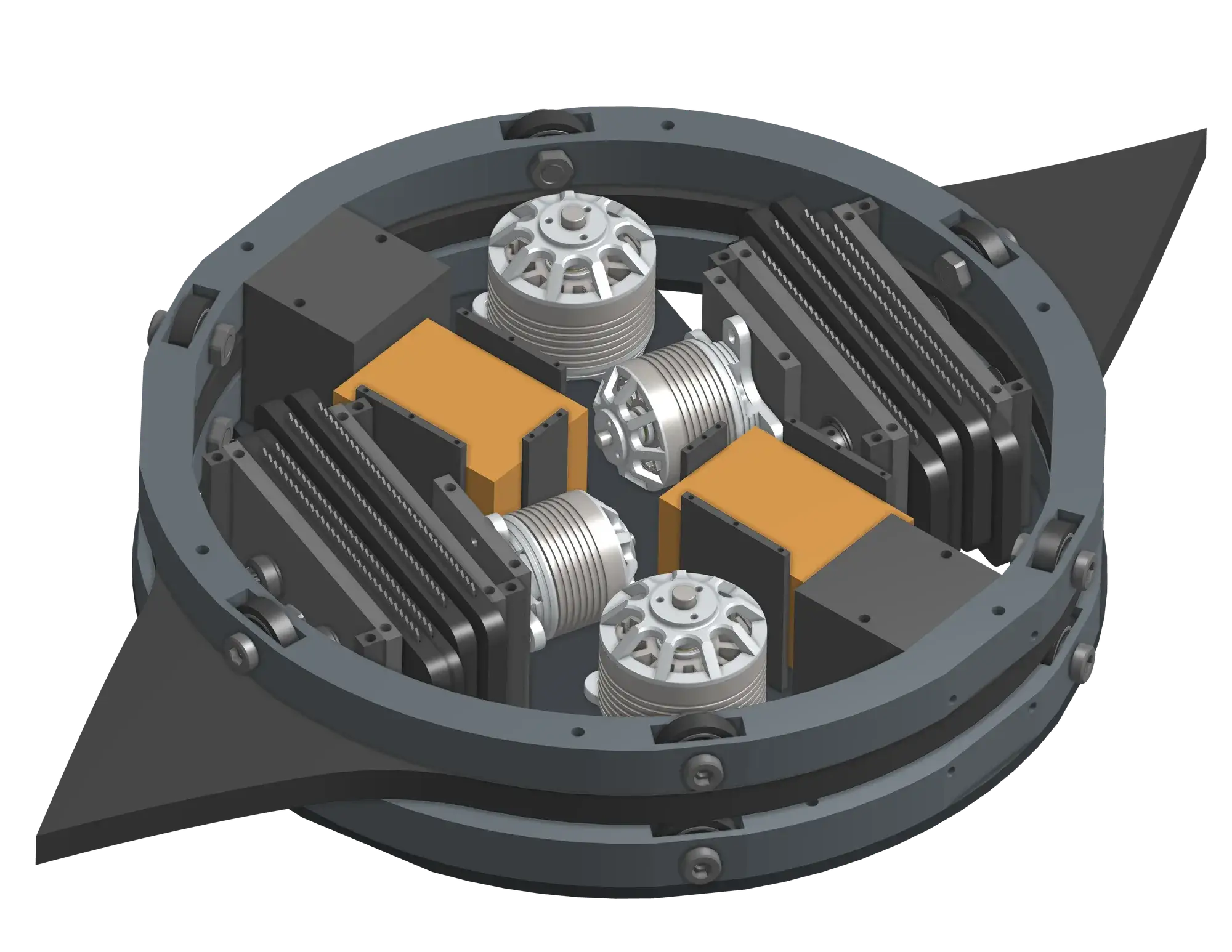
The weapon is the ring that spins around the robot, stores kinetic energy, and delivers it on impact. The constraints are hard and they pull against each other:
| Requirement | Value |
|---|---|
| Kinetic energy at operating speed | at least 3.0 kJ |
| Tip speed | above an engagement floor |
| Weapon mass | minimize, within an 8 lb budget |
| Inner bore | at least 285 mm, for packaging and the bearing |
| Ring web width | at least 7 mm, for the bearing race |
| Drivetrain | two friction-drive motors, 60 mm cans, 12S, at most 2.5 lb each |
| Spin-up | 2 to 3 seconds |
| Structure | survive tip impacts without yielding or fracturing |
| Manufacturing | one waterjet-cut plate plus CAM fillets, exportable as a 3D solid |
| Balance | center of mass within 1.25 mm of the spin axis |
Approach
I wrote a closed-loop design system from scratch that turns those constraints into a manufacturable, structurally checked part:
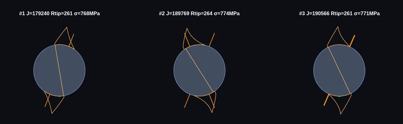
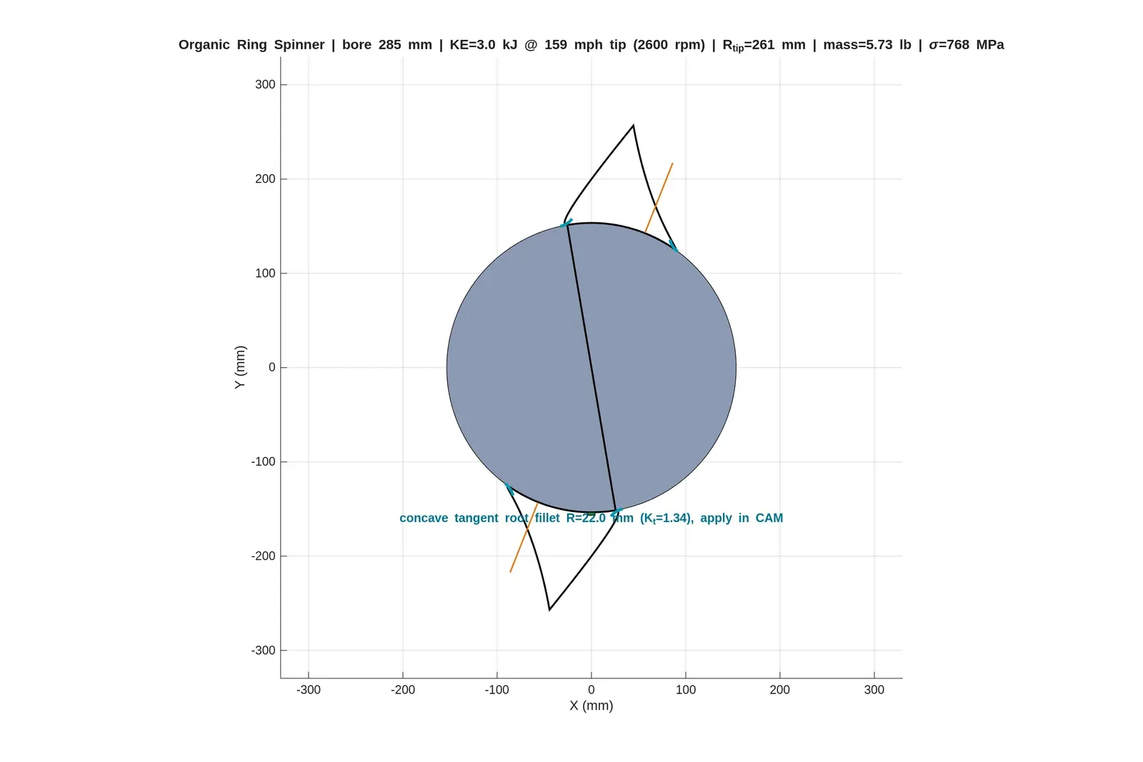
- Parametric geometry (MATLAB). Each tooth is a composite Bézier outline joined tangent (G1) to the ring, with a concave root fillet. Twenty design variables control ring radius, tooth height and width, four Bézier control points, rake, rib flanges and fillet radius.
- Constrained global optimizer. A multi-start random search with budget-doubling rounds and local refinement. Every candidate must pass hard gates for energy, tip speed, stress, deflection, balance, reach and manufacturability before it competes on minimum mass.
- Fast structural screen. A deliberately conservative model inside the loop: a tapered-cantilever beam sweep of the tooth over 24 load directions and two load envelopes, a ring-web check, centrifugal hoop stress, and a stress-concentration factor from the fillet. It is cheap enough to evaluate 104 to 105 candidates per run.
- CAD export (Python). The winning profile goes to DXF and is extruded to a watertight STEP solid with OpenCASCADE, with sliver edges cleaned up so it imports as a solid.
- Independent FEA (Python). A 2D plane-stress FEA in scikit-fem on a gmsh mesh of the real waterjet profile.
Key design decisions
- Two teeth, point-symmetric. Two teeth 180° apart on a solid steel ring put the center of mass exactly on the spin axis.
- Mass at the rim. At a fixed tip speed, kinetic energy rises with the radius of gyration. The optimizer grows the teeth outward instead of thickening the hub.
- Friction drive, no gears. Two polyurethane-padded motor cans press on the ring’s inner bore, a 4.75:1 ratio. The limit is traction: on a hard hit the drive slips instead of back-driving the motors and ESCs, which protects the electronics.
Engineering detail
True FEA
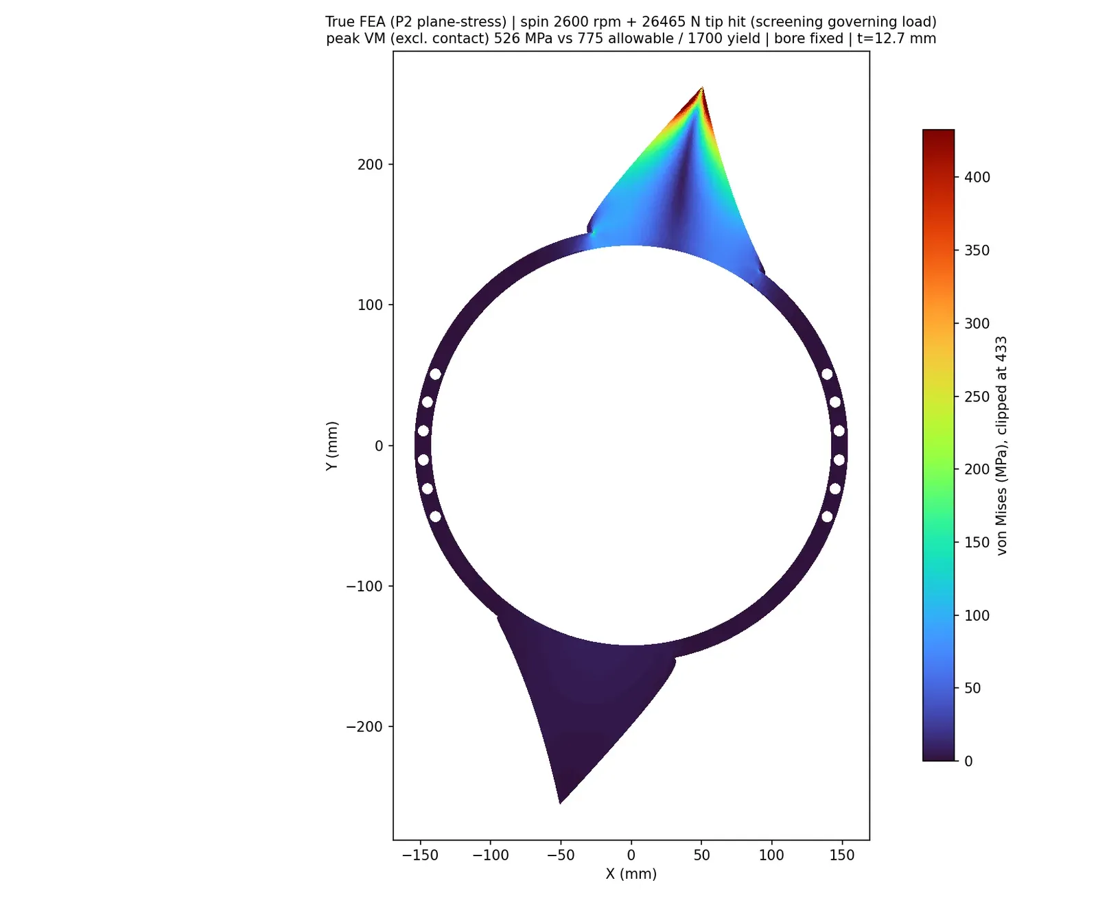
The screen is fast but approximate, so I checked it against a true finite element model: about 20,000 nodes of quadratic triangles, refined at the ring, loaded with the centrifugal body force at 2,600 rpm plus a tip-impact traction. Stress is linear in load, so I superposed the tip force on the spin state and solved for the exact load capacity by bisection.
| Load case, fixed bore | Peak von Mises |
|---|---|
| Centrifugal only, 2,600 rpm | 22 MPa |
| Plus the governing 26.5 kN tip hit | about 530 MPa, against 775 MPa allowable and 1,700 MPa yield |
| Tip force to reach the allowable | about 37 kN (8,400 lbf) |
| Tip force to reach yield | about 82 kN (18,400 lbf), a safety factor near 3 |
The screen came out about 45% conservative compared with the FEA, the safe direction for a screen. The tooth-to-ring junction is not a hotspot because the tooth joins the ring tangentially, so the fillet is fatigue insurance.
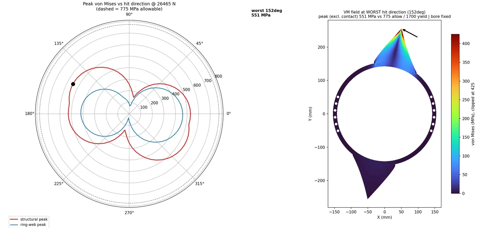
A combat weapon gets hit from any angle, so I swept the tip load through 360° using two orthogonal unit loads. The response is a two-lobe pattern: worst at the two tangential bending directions and lowest for radial hits. The worst direction raises peak stress only about 5% over a typical hit, and the design stays under the allowable at every angle.
Flaws the cross-checks caught
- A hidden ligament. With the bore fixed, the model said the weapon was sound. With the bore free (inertia relief, the correct model for a ring that floats on its bearing), it showed a severe stress riser: the lightening holes left only a 1.5 mm ligament to the bore, right where the bearing seats. The fixed-bore clamp had been propping that ligament up. I changed the optimizer’s hole rule to require a real ligament. On this thin web that removes the holes entirely, and they saved little mass anyway.
- Mass counted twice. Hole mass was being subtracted twice, under-reporting weapon mass by up to about 2.9 lb and corrupting the minimize-mass objective. I found it because the STEP solid’s volume disagreed with the analytical model. They now agree to 0.15%.
- Stresses that weren’t real. The free-body FEA reported 3,000 to 11,000 MPa at the tooth roots. The exported outline had near-180° cusps there, true singularities that grow without bound as the mesh refines. Modeling the manufactured fillet gave convergent geometry.
- Fillet backward. An early version drew a convex gusset at the tooth root where the re-entrant corner needs a concave cove. It is now a true tangent arc.
Results
| Parameter | Value |
|---|---|
| Kinetic energy | 3.01 kJ at 2,600 rpm |
| Tip speed | 159 mph (71 m/s) |
| Mass | 5.73 lb (2.60 kg) |
| Bore / web / tip radius | 285 mm / 11.0 mm / about 260.6 mm |
| Plate | 12.7 mm hardened tool steel, one waterjet part |
| Balance | 0.00 mm center-of-mass offset |
| Drive motors | about 250 to 270 KV on 12S, 1.0 to 1.5 kW each during spin-up |
What is not solved
- Tips only. At a 30 mph closing speed, the two-tooth ring wins the race to first contact and usually strikes tip-first. But the 180° gap means that in the worst case an opponent penetrates about 155 mm into a 107 mm tooth zone. Guaranteeing tip-only hits needs about 229 mph (3,750 rpm, past the energy and stress targets) or three or more teeth (against the two-tooth requirement). That trade-off is the builder’s call.
- Re-running free-body FEA on the final hole-free ring is queued. The FEA figures above are from the prior iteration.
- Impact is quasi-static. A transient contact study would refine the stresses at the tip contact.
My contribution
I designed the weapon and wrote the whole toolchain: geometry, optimizer, screening model, CAD export and FEA.