P·02 · Mechanical · Electrical
360° Survey Drone for Crack Detection
An autonomous survey drone on an open ArduPilot stack, with its camera mounts and filtering reworked to stop vibration smearing the 360° footage.
At a glance
- 2.5 Gpeak vertical acceleration
- ~55 mphtop horizontal speed
- 15–20 minflight time on a 4000 mAh pack with the survey payload
- Where
- Geolabs, Inc.
- Role
- Designer and builder
- Status
- Active
- Onshape
- ANSYS Mechanical (FEA)
- ArduPilot
- ExpressLRS
- EdgeTX
- FFT harmonic notch filtering
- IMU log analysis
- OMAX abrasive waterjet
- Carbon-fiber fabrication
- TPU 3D printing
- 3D scanning
The problem
Geolabs, the largest geotechnical firm in Hawaii, documents sites and looks for structural cracks from the air. Commercial DJI drones did not fit their needs:
- Compliance: government policy restricts DJI hardware on some of their projects.
- Programmability: they wanted an open flight controller that runs custom autonomous missions and can take AI and computer-vision code.
- Cost: it had to be clearly cheaper than a DJI system.
- Endurance: 15 to 20 minutes of flight while carrying survey cameras.
- Modularity: interchangeable cameras and sensors for different missions.
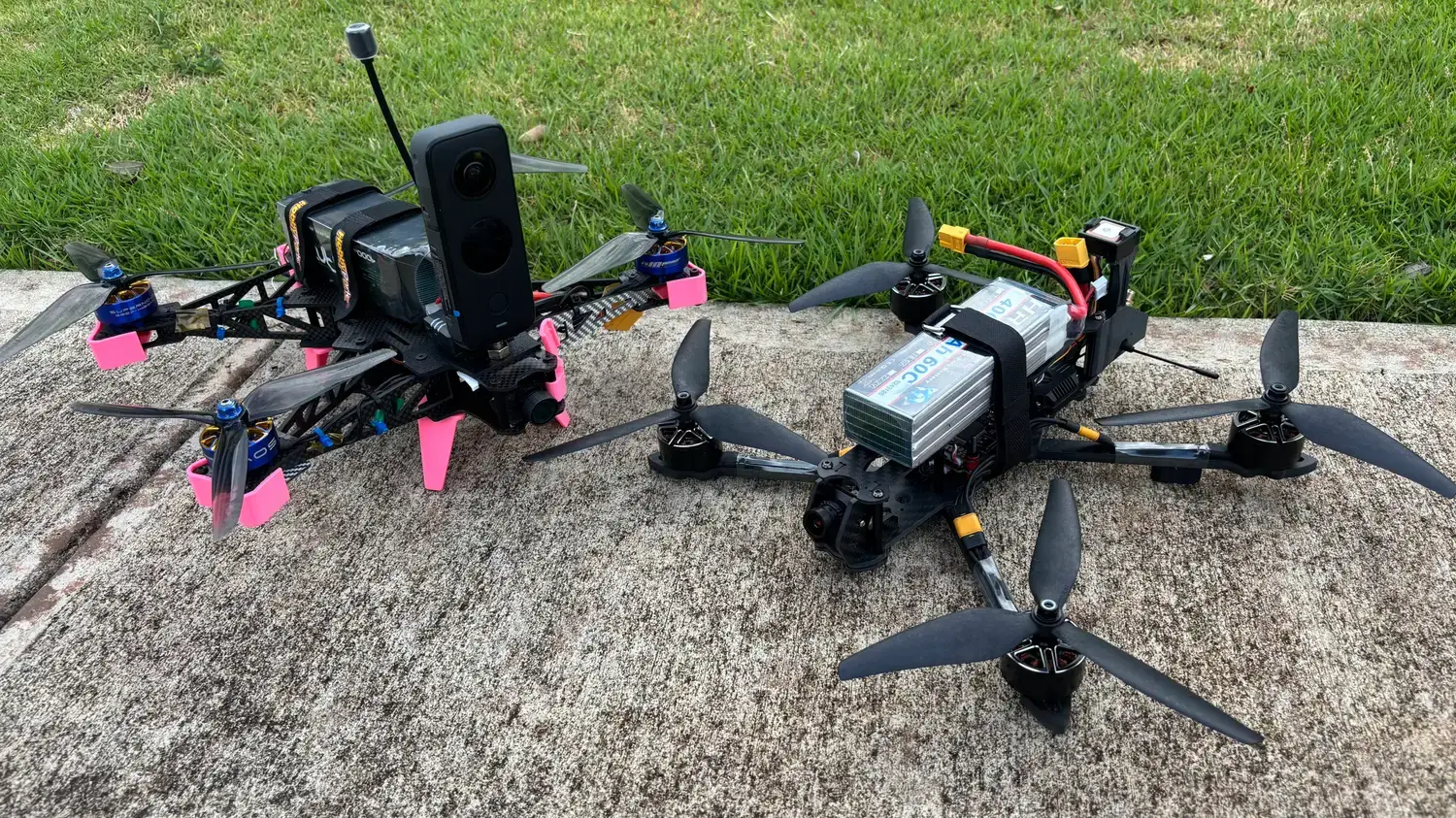
No off-the-shelf drone met all of these, so I designed and built one. This page covers the 7-inch 360° capture build. It is one of four drones in the Geolabs site-mapping program, which span 5- to 15-inch propellers. The motor controller I designed for the program has its own page, and so does the photogrammetry flow survey.
Approach
An open stack instead of DJI
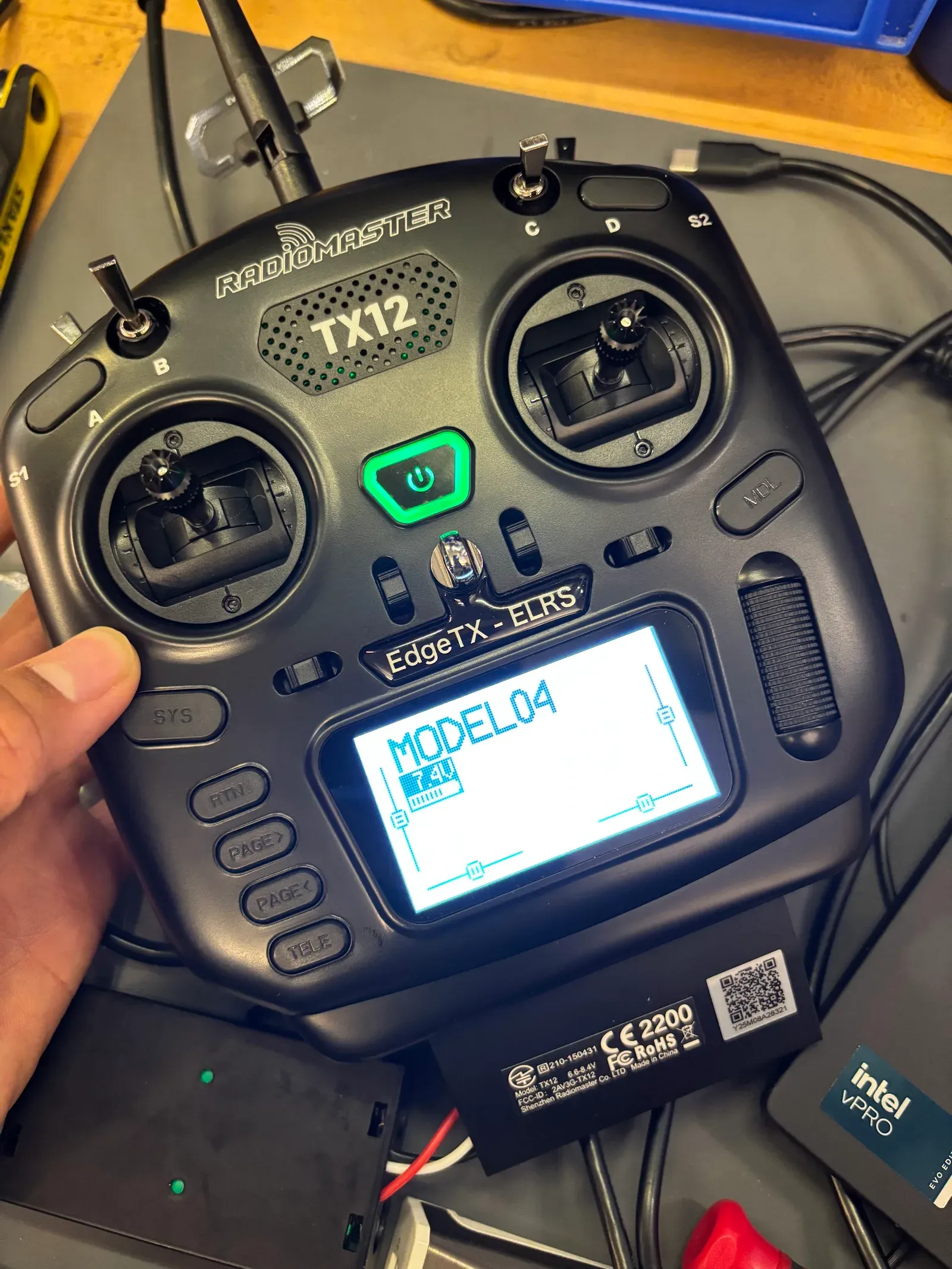
The flight controller runs ArduPilot for autonomous waypoint missions, with a RadioMaster TX12 transmitter on the ExpressLRS protocol for long-range control. Both are open, which is what makes custom missions and onboard vision code possible.
Components picked for clean data
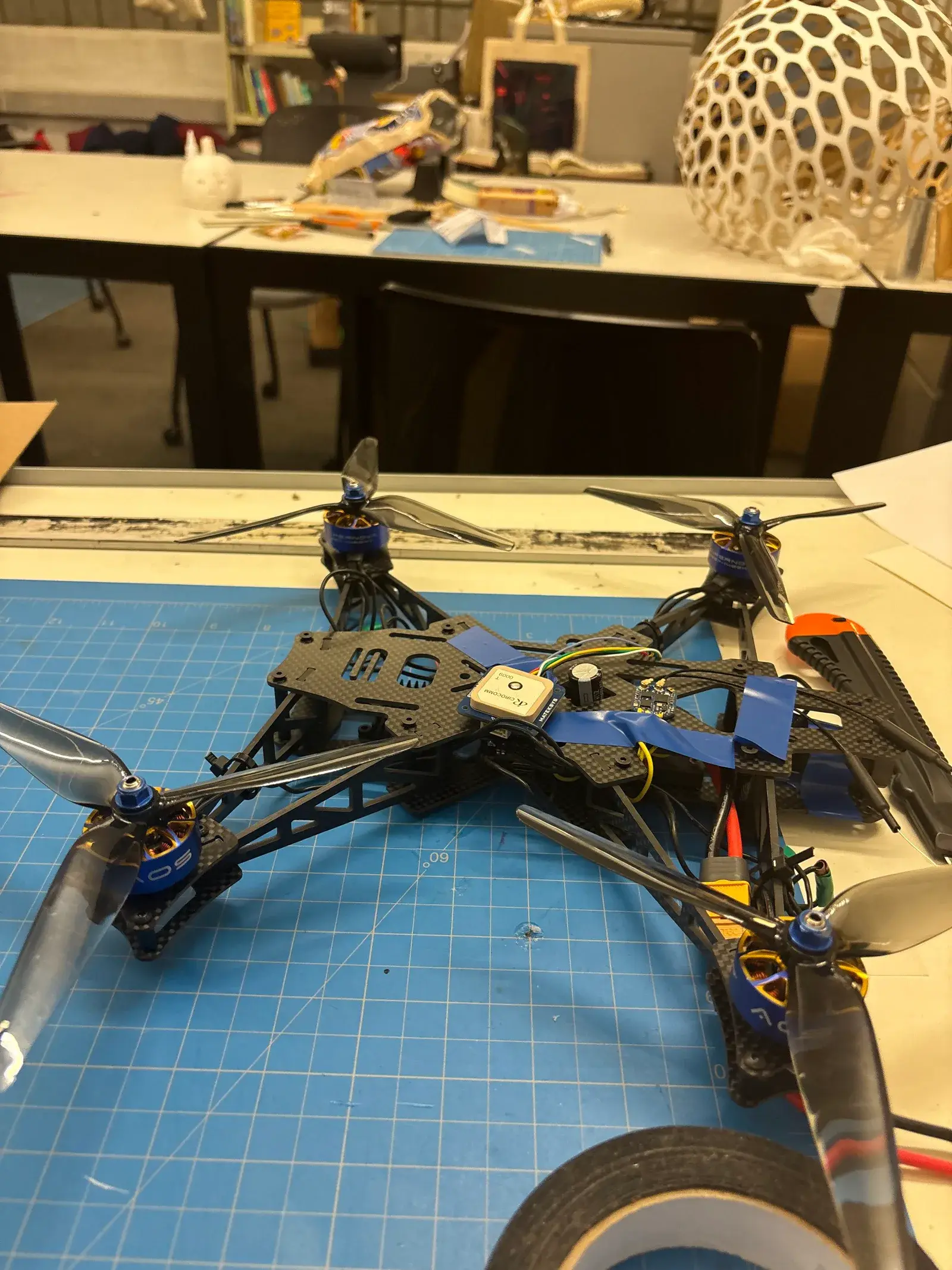
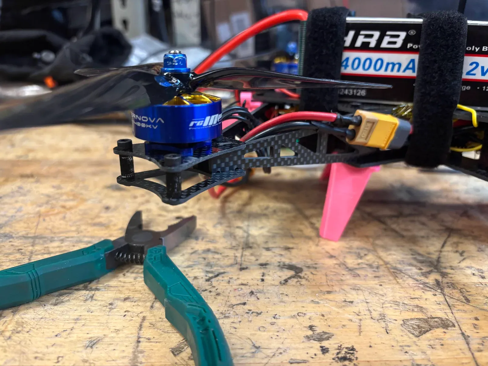
- Frame: an iFlight XL7 Evo in carbon fiber, chosen to minimize vibration so the IMU and gyroscope data stay accurate.
- Propulsion: AOS Supernova 2807 low-KV motors on 7-inch propellers, for torque and efficiency under payload.
- Battery: 4000 mAh, for 15 to 20 minutes of flight.
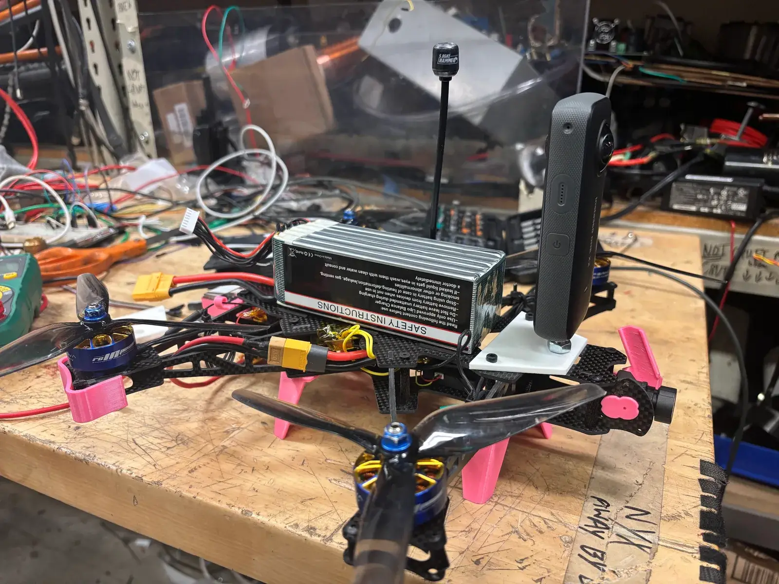
- Cameras: a Caddx FPV camera for the live piloting feed, and an Insta360 at 5.6K for 360° site documentation.
Everything modeled first
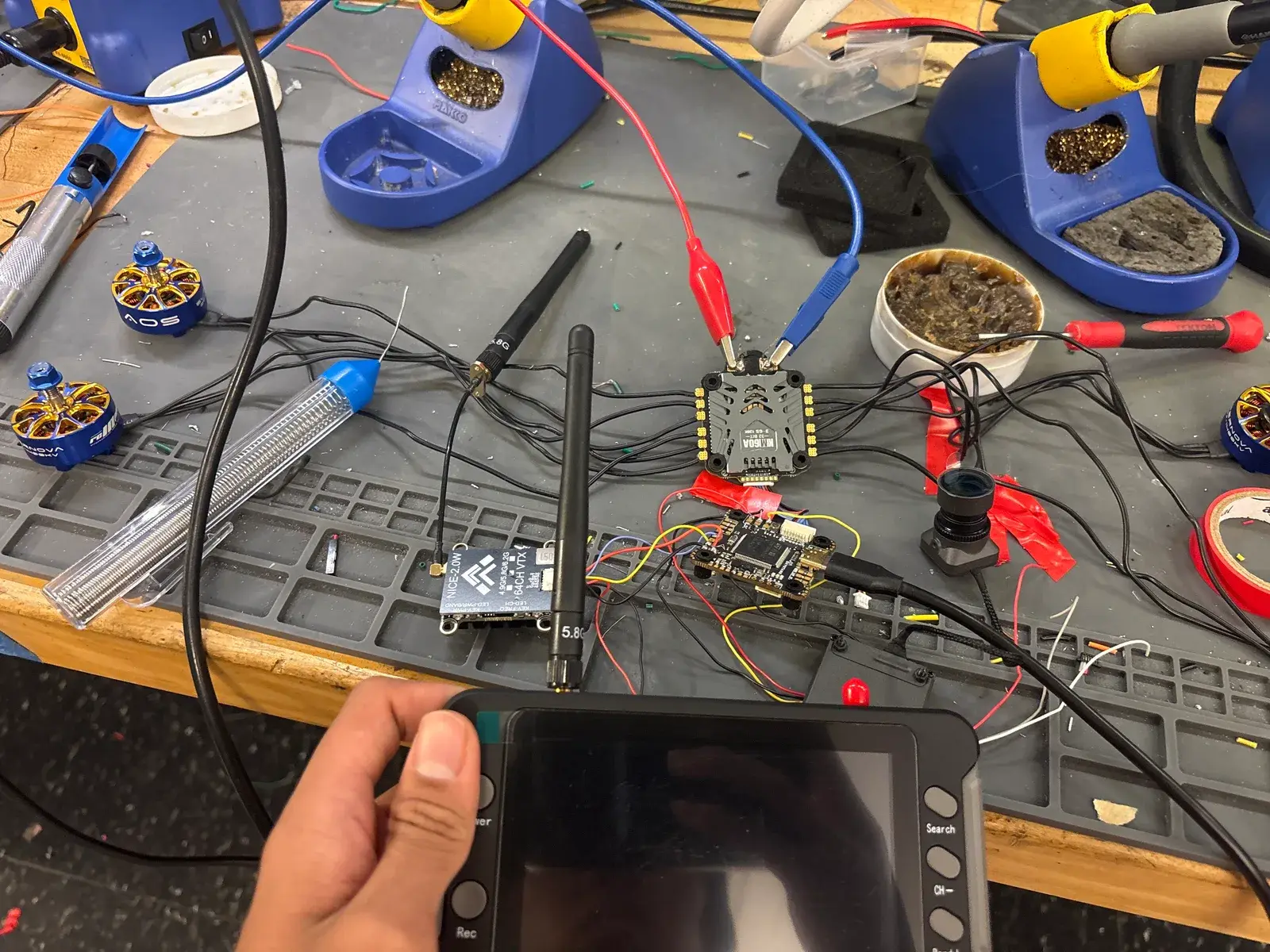
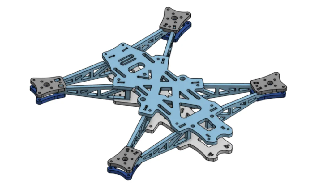
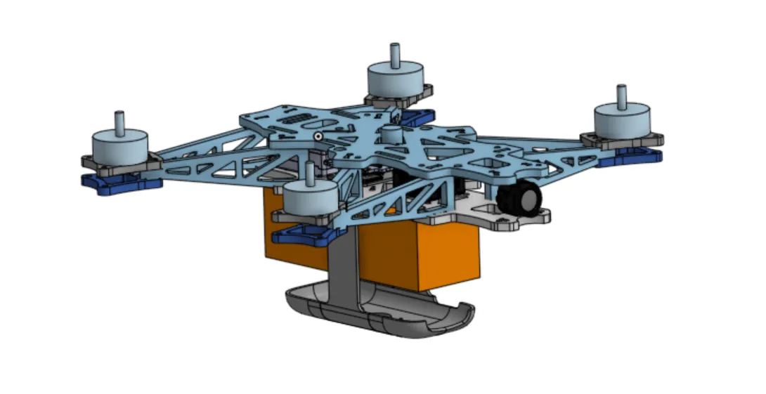
I modeled every component in Onshape, including the frame modifications for the camera mounts and the payload bay. For the ground station, I 3D-scanned the TX12 and designed a mount that holds a monitor directly on the transmitter, so the operator watches the feed without a separate screen.
Engineering detail
Vibration: tuning it out
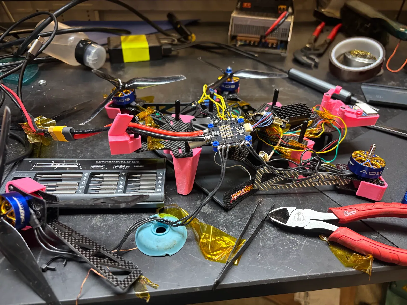
Motor and propeller vibration shakes the cameras and corrupts gyro data. I recorded raw IMU gyro data on test flights and ran frequency analysis to find the dominant vibration modes from the motor-propeller interaction. ArduPilot’s FFT-based harmonic notch filter then tracks those frequencies and their harmonics during flight and removes them. That cut the resonance reaching the cameras and removed the gyro noise that would otherwise degrade flight stability.
Vibration: the mount that flexed
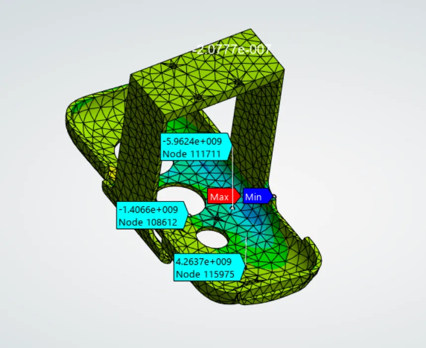
My first camera mounts were 3D-printed PLA. Field testing showed they flexed under motor vibration, and the footage was visibly degraded. I ran FEA on the mount geometry in ANSYS under realistic loads, including a light-crash case. It showed the PLA part lacked the stiffness to stop micro-movement in flight and would fail on impact.
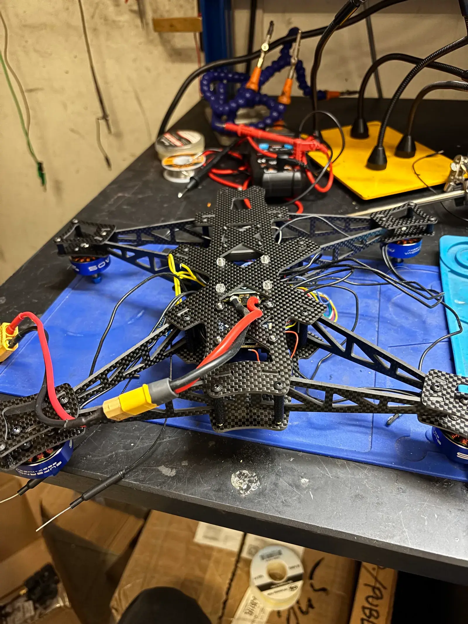
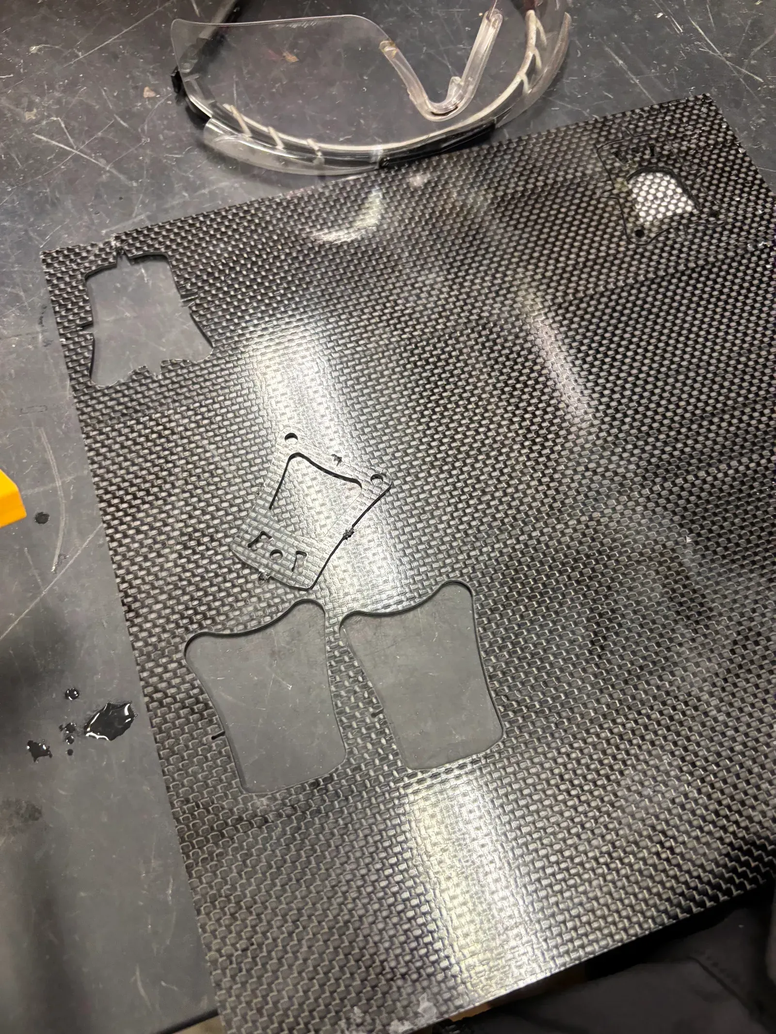
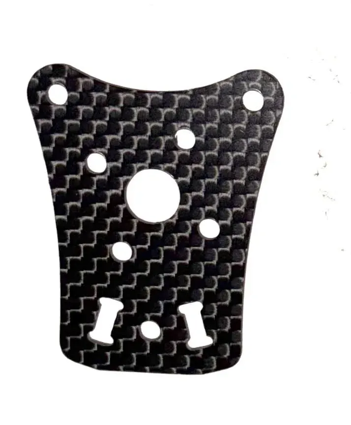
I rejected reprinting the mount in PLA and moved to carbon-fiber sheet. I learned to run an OMAX abrasive waterjet and cut the mounting plates from sheet, which gave the rigidity with little added weight. The Insta360 now sits on top of the frame on the carbon mounts, with TPU bumpers protecting the camera and lens. The FPV camera mounts at the front in a TPU housing, and the receiver antenna exits the rear through a TPU routing channel. The structure was validated in FEA before it flew.
Testing
Results
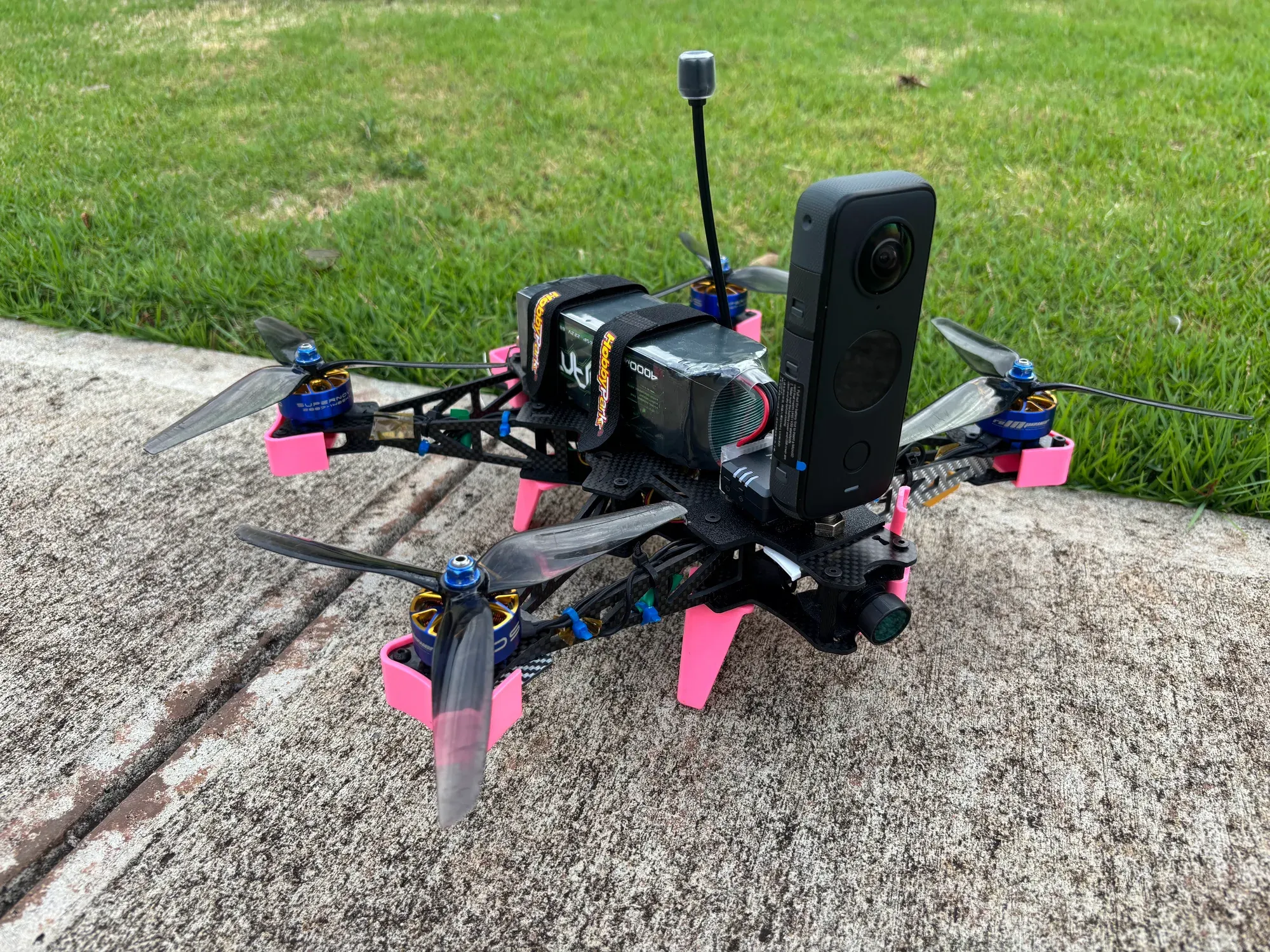
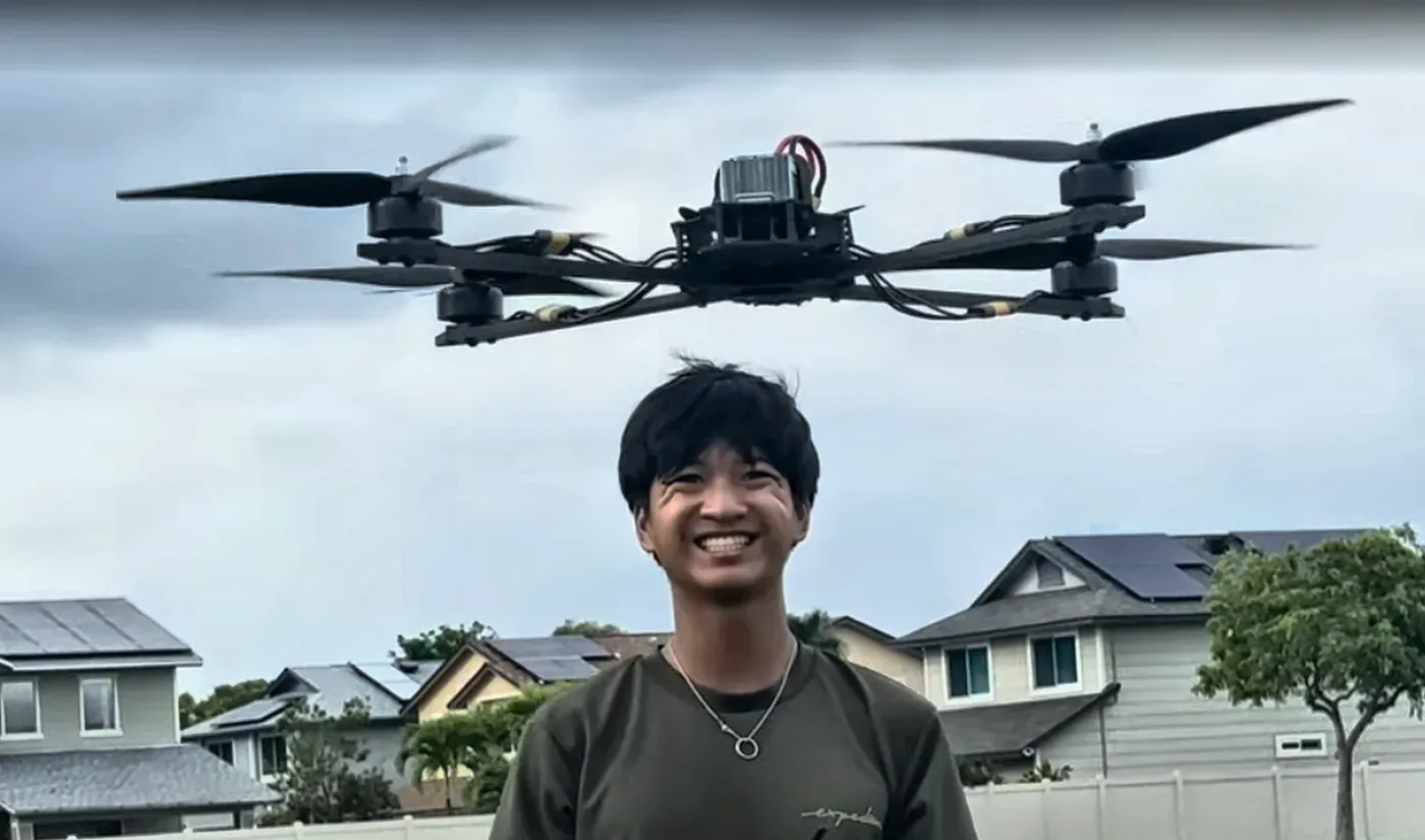
The finished drone reaches about 2.5 G of vertical acceleration and about 55 mph horizontally, and flies 15 to 20 minutes on a 4000 mAh pack with the survey payload. It flies programmable waypoint missions for repeatable documentation, captures 360° imagery, and its mounts accept thermal cameras, lidar or other sensors. The hardware and software are open, so it meets the projects’ DJI restrictions at a lower system cost than a commercial drone.
What did not work: the first PLA camera mounts, which flexed and smeared footage until I replaced them with carbon fiber.
My contribution
I selected the components, modeled the drone and its mounts in Onshape, designed the transmitter monitor mount from a 3D scan, tuned the notch filtering from flight logs, ran the mount FEA, cut the carbon parts on the waterjet, and built and flight-tested the drone.
Gallery
4 images